Building a muscle (EMG) controlled hand exoskeleton
For my final-year engineering project I was tasked with building a hand exoskeleton that is controlled using EMG signals (your muscle signals, De Luca1 has some good info on EMG signals’ biochemical processes and characteristics if you’re interested). The goal of the project is to help people that are affected by hand paralysis, with the idea being that they can then control their hands using the exoskeleton to hold objects. My initial plan was to throw the (very) noisy and small EMG signals into a neural-network and let it figure it out by itself. Turns out machine-learning algorithms are actually quite dumb. That didn’t work, however after a year long of building a lot of instrumentation amplifiers, strange sensors and painstakingly ripping electrode stickers from my arm I got to something usable. TLDR; it can classify five gestures with an average accuracy of 92% (at least on me). Apart from that it can also figure out with what force you want to open and close your hand, and it also makes sure that you don’t dislocate your fingers while doing so.
The basic design
The idea was that I wanted to be able to open and close a user’s fingers by using the signals their muscles naturally emit while trying to perform the intended movement. To do this I needed to read their EMG signals through some electrodes on their forearm (or actually, basically anywhere, but doing it on their forearm allows you to control the exoskeleton using your natural finger movements), do some feature extraction and then pass it on to the classification algorithm. Apart from this I also needed to perform mechanical control on a hand exoskeleton, which includes force feedback and also some safety checks.
To read the EMG signals you need some instrumentation amplifiers and filtering. The EMG signals are on the order of about 1.5mVrms (in my case I found it to be a lot smaller, more on that later), so the amplifiers are going to have to have quite a bit of gain. Luckily, the signals are rather low frequency (<500Hz) so that made things a bit easier.
Then, once the signals were in the Volts range I could sample them using a micro-controller, and start doing some processing on them. Once sampled, the signals are first passed through a bunch of feature extraction algorithms to get them in a usable form, and once that is done, they’re plugged into a neural-net for the actual classification. The job of the classifier is to figure out which one of five gestures you’re trying to perform (or if you just want to do nothing, i.e. hold). Once the classification is done, it’s on to the actuator control algorithms.
The exoskeleton was powered by a bunch of small motors pulling on some strong fishing line. The positions of the fingers weren’t really that important, as I was not trying to predict continuous hand kinematics. Rather, which is more important, is the force feedback from the exoskeleton. Instead of opting for force-sensing resistors I chose to use the motor current as force feedback - it ended up working very reliably and required no additional sensors (and wiring to the hand) which was a big win since those force-sensing resistors (essentially strain gauges, but flexible and smaller) are unreasonably expensive.
And as they say, safety last. I added some extra features to detect if the fingers were bending too far, current limiting resistors to protect you from 3.3V accidentally touching your skin (I even had to get ethics clearance for this) and also an emergency off switch in case of, you know, it gaining sentience and trying to kill you.
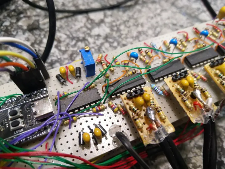
The EMG amplifiers
To read EMG signals you need to use a high gain, high input impedance instrumentation amplifier with some high- and low-pass filtering to get rid of noise and movement artefacts. I couldn’t use any off-the-shelf IA chips like the AD620 as I wouldn’t get credit for the design, so I opted for the classic triple-opamp IA. Following the recommendations from The Art of Electronics’s IA section I was able to get a fairly high CMRR without resorting to any crazy resistor tolerances or special opamps. Pairing that with shielded cables and a low-impedance ground reference electrode (see 1 for details on electrode placement), on a good day the EMG signals were almost completely mains-free.

EMG control model
If it’s not clear from the previous image, EMG signals are pretty useless in their raw form. They are noisy and are plagued with cross-talk between muscles. One of the main muscles that control the finger flexion is the flexor digitorum profundus 2 (don’t quote me on this, my biology knowledge is laughable). Unfortunately, as all the fingers’ muscles are grouped together, you cannot easily separate the signals based on what finger is activating. So, to separate the finger activation signals I employed a few feature extraction algorithms and machine-learning. The feature-extraction algorithms mostly consisted of simple time-domain features (things like the RMS value and zero-crossings), but I also added the Wavelet transform, a time-frequency domain feature, which is a operation that essentially bandpass filters the signal at different frequencies (this explanation is lacking spectacularly, but I’d be hard-pressed to properly explain it correctly so this is what you get). This resulted in a feature vector that was relatively robust against the errors caused by placing electrodes on slightly different positions in different usage sessions. Three EMG channels were used (two on the FDP muscle and one on the EDP, for hand extension) and the feature extraction algorithms were executed on each channel and then fed into the classification model.
For the classification model, I made use of a neural-network. They tend to be fairly widely used in the field of EMG classification and are fairly efficient when implemented on an embedded model (not talking about training here, just inference). Using a neural-network has its downsides though, as I had to collect a lot of data before the model generalized well (I needed to collect about 1 hour’s worth of EMG samples from myself for the final model I used, many more hours for testing). I generated labelled datasets by using a simple button interface. When I executed a gesture, I just pressed the corresponding button with my other hand - the micro then paired the EMG samples with the pressed buttons and transmitted that to my PC for training.

The neural-network was then trained as a multi-class classifier, with each output corresponding to one of the gestures from the diagram above. A classification accuracy of 94% was achieved on a validation dataset. I later also verified the classifier’s real-world performance using the same button interface I used for collecting the training data - the classifier’s output, along with the true value (that I provided by pressing the corresponding button) was compared and I got a classification accuracy of 92%. Each gesture was not similarly accurate however, with the pinky being the peskiest.

I ran into a few interesting issues with the classification model:
- Interestingly (or not, depending on your expectations), training the model on multiple user’s data decreased the classification accuracy and, in some cases, the model wasn’t even usable after training. I expected there to be more similarities between the EMG signals of different people. So, for each person that uses the exoskeleton a unique model had to be trained.
- Once I started actuating the motors, they started introducing low-frequency noise on the power rails due to their inrush current. Adding bypass caps improved the situation somewhat, but the inrush dips were stubborn as I had a reference voltage generated using a resistor divider (the trimpot) from the rails, which had some serious gain on it. These low-frequency dips and spikes which now presented themselves in the EMG signals sometimes caused the classification model to start making errors and causing interesting feedback loops where the classifier would start the motor, and the motor would cause the classifier to make a certain classification again leading to oscillation. I solved this by making the motors activate during training - this means the power rail dips were present in the training data as well, and consequently the classification model was able to successfully reject the noise.
- Mains noise pickup was inevitable, sometimes a power cord would lie on the floor touching my feet, and it would significantly increase the mains noise in the EMG readings. Following the same approach as with the motor noise, I purposely including training data with significant (and not so significant) mains noise, which again improved the classifiers real-world robustness.
Force estimation
Now that I had the gesture classification working I had to had force estimation, i.e. the exoskeleton needed to adjust its applied force using the EMG signals as the control. The harder you close your hand, the harder the exoskeleton should close itself. I’ll get to how the exoskeleton measured its applied force at a later point, but for now just assume it worked. When you perform stronger contractions with your muscles, the RMS value of the EMG signals start to also increase, which means that you can use the RMS value as a relative indicator of contraction strength. However, just using the RMS value from the EMG signal directly is perilous - what happens if you stand on a wire causing a large mains noise component in the signal? Have a look at the following frequency analysis of an EMG signal in the presence of some mild mains noise - you’ll see that mains magnitude can easily dominate the actual EMG signal, including the RMS estimate.

The thing is, mains noise isn’t the only issue - if something causes an electrode to move on the skin, that also creates significant low-frequency noise. So the whole low-frequency region can cause the RMS value to wildly fluctuate. To remedy this, I did some digital low-pass filtering on the EMG signal before calculating the RMS, as the higher frequencies tended to be less affected by noise. The filtered signal’s RMS could then be reliably used for force-estimation.
Measuring force in the exoskeleton
Now that I had the “how hard” part figured out from the EMG signals, I needed the exoskeleton to actually know how hard it was actually squeezing.
The direct solution here is to use some Force-Sensing Resistors (FSRs) on the fingertips. These are little pads that change resistance when you press on them. They are accurate, reliable, and unfortunately, unreasonably expensive for a student budget. Plus, running wires all the way down to the fingertips is a mechanical nightmare waiting to snag on a door handle.
So, I decided to use the motor current as a proxy for force. The physics here is actually pretty convenient: the torque a DC motor outputs is proportional to the current it draws. If the exoskeleton tries to close the hand and hits an object, the motors stall, and the current spikes. By measuring that current, I can infer how much force the fingers are exerting.
To implement this, I used a simple current shunt resistor (a resistor with a very low resistance) in series with the motors. By measuring the voltage drop across this resistor, the microcontroller could monitor the current in real-time.

This setup allowed for a closed-loop control system without a single sensor on the actual glove. The microcontroller simply checks the motor current against a dynamic threshold calculated from the EMG signal. If the motor current (actual force) exceeds the EMG-derived threshold (intended force), the motor stops. It turned out to be surprisingly reliable, effectively preventing the exoskeleton from crushing things (or the user’s fingers) while saving me from wiring hell.
Real-time inference on the microcontroller
The real challenge with the neural-net approach was getting it to run, in real-time, on a very constrained microcontroller.
Standard microcontrollers often struggle with the heavy floating-point mathematics required for neural networks. To address this, I selected an STM32 microcontroller equipped with a hardware Floating Point Unit (FPU). This hardware allowed the system to perform single-precision (32-bit) floating-point calculations natively, avoiding the severe performance penalties usually associated with software-based emulation.
Rather than attempting to run a heavy interpreter like TensorFlow Lite, I took a more direct approach. I exported the trained weights and biases from the Python model and embedded them directly into the microcontroller’s flash memory as static C arrays.
The inference loop operated as follows:
- Data Acquisition: The system records EMG data for a 200ms window.
- Feature Extraction: Next I extracted specific time-domain features—such as Zero-Crossings and Slope Sign-Changes - rather than processing the raw signal. This compressed the input into a manageable vector.
- Calculation: The microcontroller performs matrix multiplication using the extracted features and the stored weights (this made use of the hardware-accellerated FPU)
- Classification: The output provides a probability score for each gesture. The system selects the gesture with the highest probability (e.g., “Index Finger Flex”) to drive the motors.
This approach, combining hardware acceleration with efficient feature extraction, ensured the inference process was rapid. This left ample processing time for the safety state machine to monitor limits and prevent mechanical failure.